Shematics and explanations are coming soon !!!
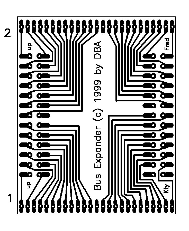
Download the PSpice compatible schematic of the Bus Expander. The pcb is 32mm x 40mm... Convert into inch if necessary !!
|
 |
 |
|
|
|
Mapped Devices
| Description | Download ! | Documentation | Pictures and Schematics | History |
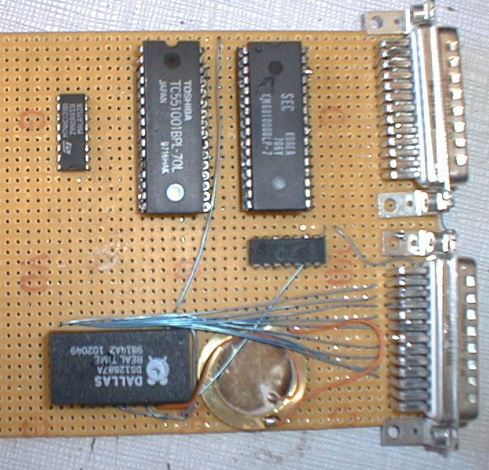
Haven't you never dreamed (....hummm) of 3Mbytes of more memory on your calc ?
Or maybe you prefer the memory + a real time clock ?
Or, maybe again, you have your own idea of what device to mapped... a floppy disk or a thermal sensor ?
Ah, ah, ah here you'll find all the informations needed to do that :)
For the moment, not to much. Don't forget to check out: Marvin and Jean-Jacques MICHEL's page.
Shematics and explanations are coming soon !!!
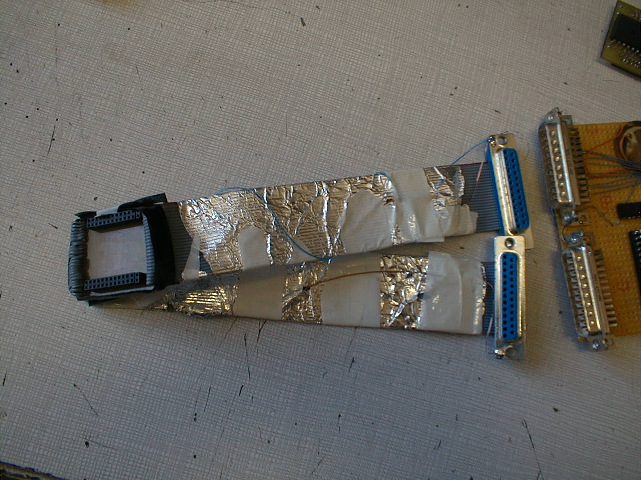
Download the PSpice compatible schematic of the Bus Expander. The pcb is 32mm x 40mm... Convert into inch if necessary !!
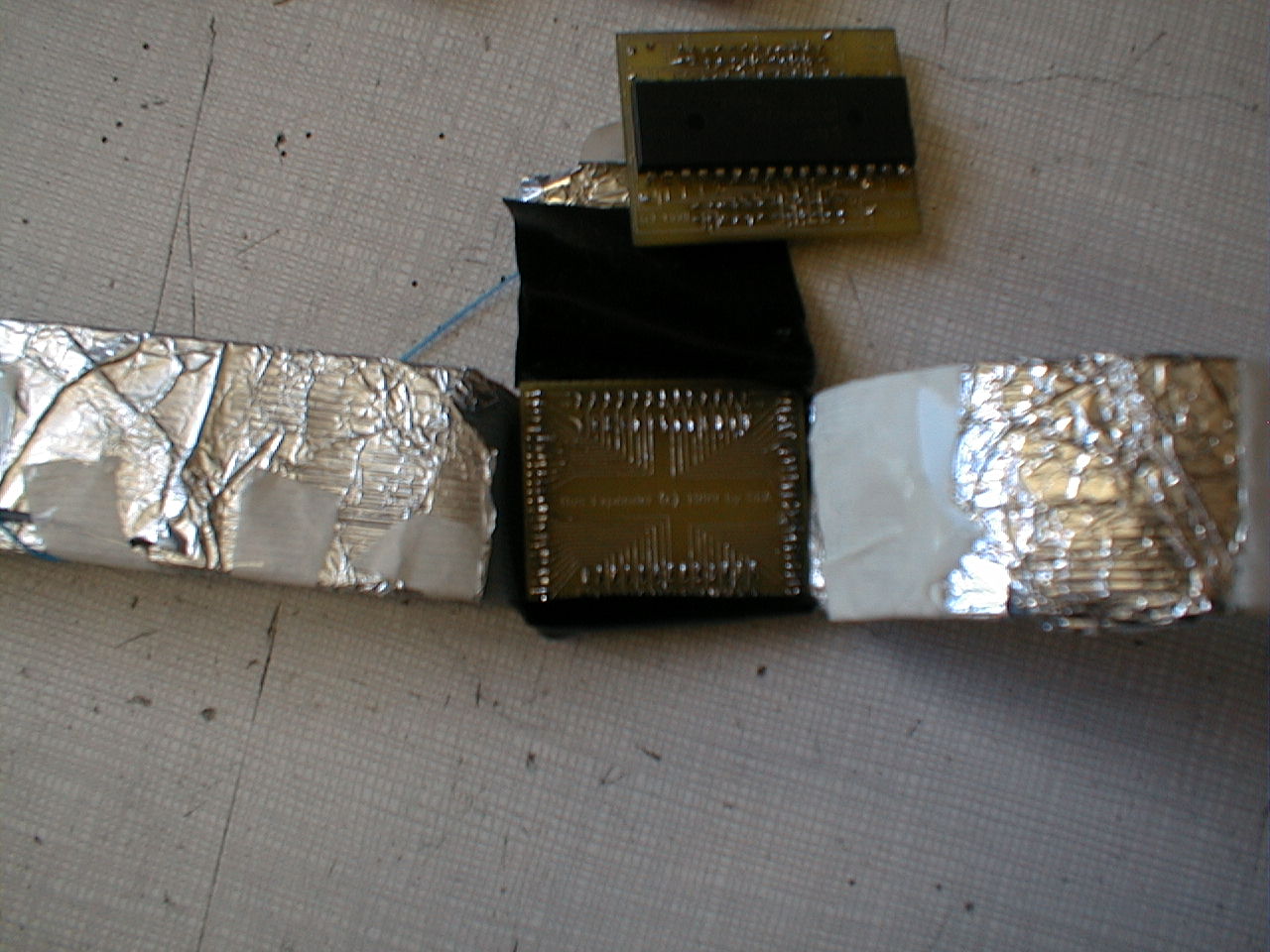
Check out how to expand the capabilities of your TI92 !
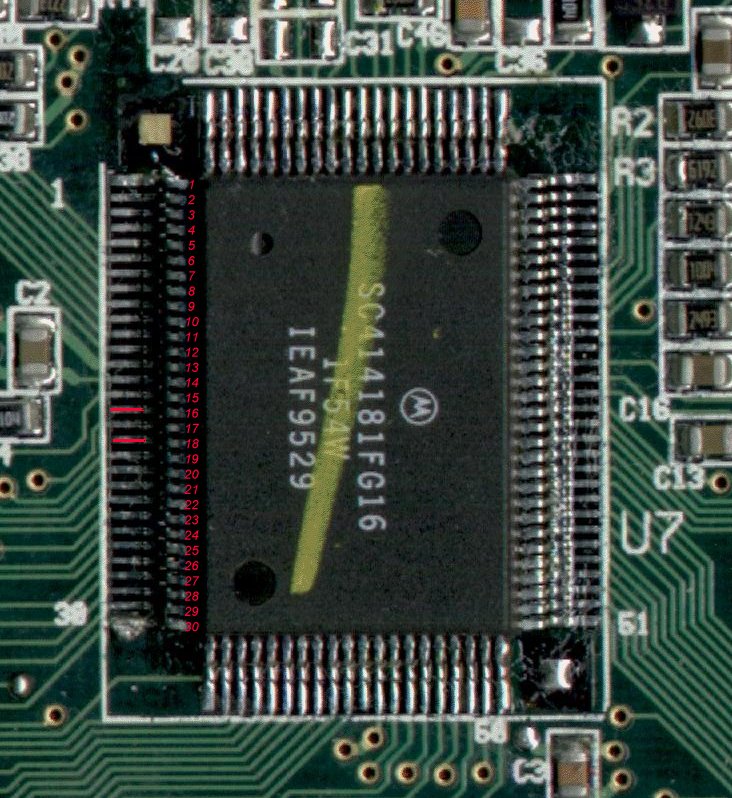
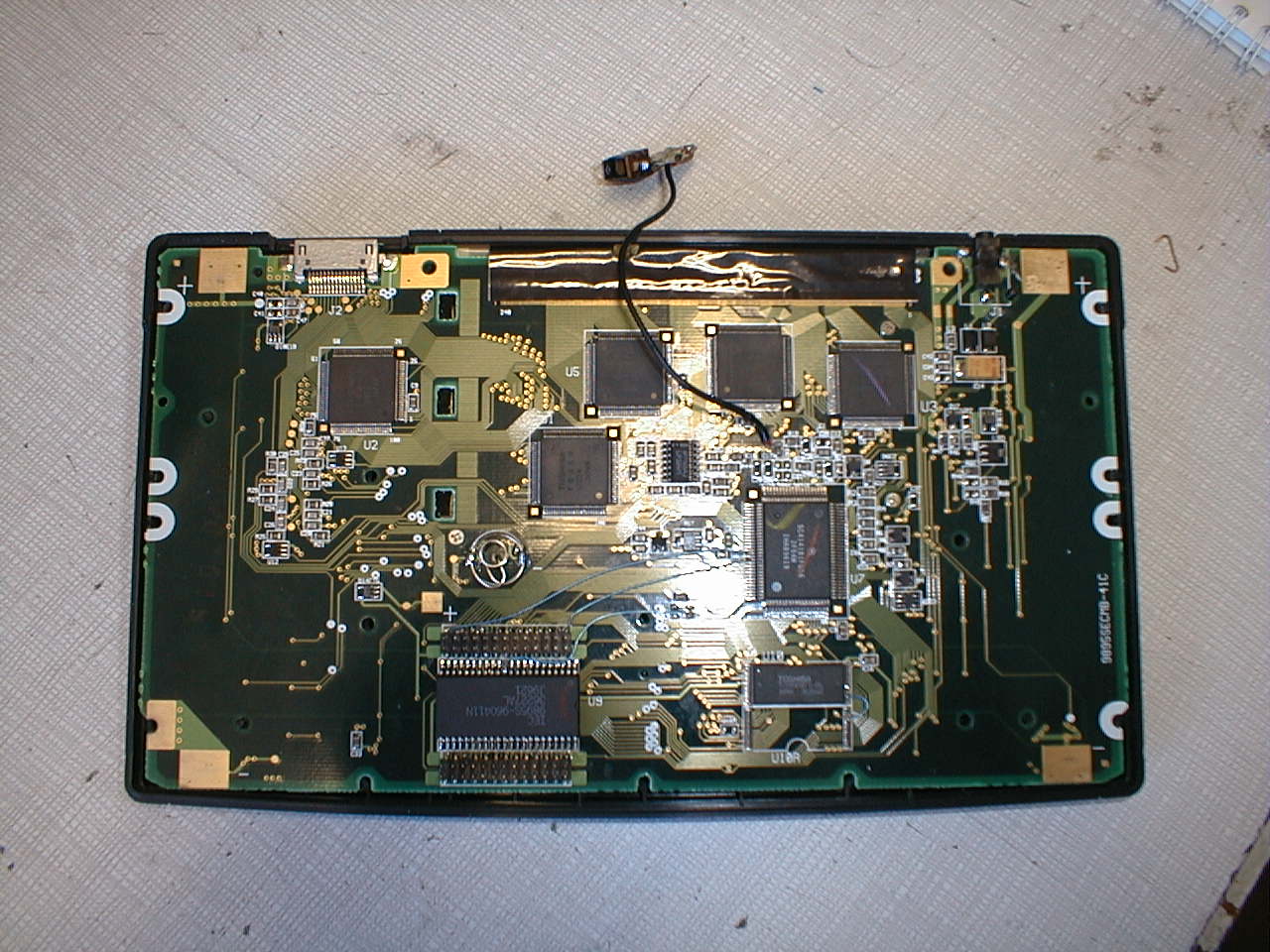
To use the Bus Expander, you'll need to solder (only) 2 wires on the TI92 mainboard. We have found that on our TI92 mainboard the following pins aren't used by the calc. Well, actually you have to connect those pins in yellow below to correspondant CPU pins (!):
- Upper left pins to pin 16 of the CPU, CS4 (Chip Select at $C00000)
- Upper right pins to pin 18 of the CPU (CE1 RAM in 8 bits access mode)
Be CareFULL! That's NOT an easy part. And of course, neither DBA nor Texas Instruments, could be responsibles in ANY way for what you are doing. You also need a very precise solder iron. PLEASE GIVE UP if you can't handle it...
CS4
Pin 16
CE1/ RAM
D3
D2
D1
D0
GND
A1
A3
A5
A7
A18
CE1/ RAM in 8bits access
Pin18VCC RAM
RW/
D11
D10
D9
D8
GND
CE/ ROM
A2
A4
A6
A8
A19
TI92 Bus Connectors are 2x13 pins (2mm spacing between pins). VCC RAM
?
VCC ROM
D12
D13
D14
D15
VCC ROM
A16
A14
A12
A10
A20
?
CE2 RAM
D4
D5
D6
D7
GND
A17
A15
A13
A11
A9
?
DBA 1999 |